


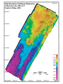
SM 2000 multibeam bathymetry (1-meter grid-cell size), overlaid on Imagenex pencil beam sonar (3-meter grid-cell size) collected by the autonomous benthic explorer (ABE) autonomous underwater vehicle on the Submarine Ring of Fire 2002 expedition to Explorer Ridge, NE Pacific. Click image for larger view.
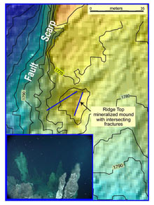
This map shows high resolution bathymetry collected from ABE in 2002 on Explorer Ridge. Contours are at 5-meter intervals. The mineralized mound consists of a base of metallic sulfide debris topped by small active chimneys composed of sulfide and sulfate minerals. The pixel size for the SM2000 multibeam bathymetry is 1 meter. This clearly shows the intersecting fracture pattern forming the mound that can also be seen on the photograph (bottom left) taken by the ROPOS remotely operated vehicle at approximately the position shown by the arrow (looking N to NE). Two lines of chimneys converge from left and right (W and E). In contrast, the effective pixel size of the multibeam data collected by the surface vessel is 35 meters, the length of the scale bar. Click image for larger view.
Mapping the Deep-sea Floor
Bob Embley
Chief Scientist
Geophysicist
NOAA Vents Program, PMEL – Newport, Oregon
A map is a symbolic construction that relates visual features seen by the human eye (or a camera) to the broader context of its surroundings. This is relatively easy to do above sea level, because maps can be produced directly from images made by satellites or planes. However, it is still challenging to produce such a map of the ocean floor, because light does not penetrate more than about 100 meters (328 feet) in seawater and the red end of the spectrum fades within a few meters.
The technology to map the sea floor has evolved rapidly over the past decade with the advent of continuous and highly precise navigation from global positioning system (GPS) satellites for the surface vessel, and advances in sonar and undersea vehicle technology. Sonar systems mounted on ships can precisely map shallow areas, but as water depth increases surface sonars become less precise due to losses from absorption (greater at higher pitched sound) and the spreading of the sonar beams at the edges. The only effective method of precision mapping in deeper water is to bring the sonar down near the sea floor.
Traditionally, this was accomplished by towing sonars on long cables, but this technique is slow and inefficient because of the drag from the long length of cable needed for deep-water surveys. The past decade has seen the rapid evolution of “autonomous” underwater vehicles (AUVs), battery-powered robots capable of completely autonomous operation. These vehicles are now extensively used by industry, the military, and the oceanography community for a wide range of projects. However, there are still relatively few AUVs capable of mapping the deep sea floor due to the challenge of navigating the vehicle precisely enough to take advantage of the accuracy and precision of the new very high-resolution sonar systems (about one meter precision). The autonomous benthic explorer (ABE) uses a combination of fixed sea-floor sonar beacons to triangulate on, and a bottom sonar Doppler logger that precisely tracks the motion of the vehicle with respect to the sea floor.
We need to be able to relate what is “seen” through the lens of a video system on a submersible to a feature on a sea-floor map in order to relate it to the larger picture of the sea-floor geology. For example, a submersible can image a mineral mound with its camera system, but seeing the mound shape on a high-resolution sonar map allows us to place the mineral deposit in the context of the region’s geology, possibly leading us to additional discoveries of mineral deposits based on the sonar map alone.